한국산학기술학회논문지 Vol. 11, No. 3, pp. 931-942, 2010
931
한국산학기술학회논문지 제11권 제3호,
2010
A Ubiquitous Home Network System for Managing Environment-Information Sensors using Image Processing
Sung-Hwa Hong1*, Suk-Yong Jung1
Abstract
A home network provides users with a variety of information services. The kind and quality of the services can be substantially enhanced by utilizing a variety of data from sensors. However, home networks currently limit their potential by focusing on providing multimedia services rather than services utilizing sensor data. Outdoor electronics are frequently made in a form that emphasizes only certain limited functions in contrast to home appliances. Thus, sensors with one or two functions rather than many can be used in outdoor systems and their use will be more economical than using sensor nodes indoors with more complex home appliances. In this study, we chose to work with motion sensors as they have many potential uses, and we selected a parking lot control system with to use the motion sensors. This parking lot control system was implemented and applied as part of a home network. For this purpose, we defined and implemented a protocol to manage the network in a ubiquitous sensor network environment for the wireless home network in this study. Although a network management system in a Ubiquitous Sensor Network (USN) related to this study is being advanced for other projects, the protocol interface and message system have not yet been clearly defined for use in a general purpose network or in an extension into heterogeneous kinds of networks, communication support, etc. Therefore, USN network management should be conducted for management of faults, composition, power, and applications. To verify the performance of the protocol interface designed in this study, we designed and implemented the necessary units (sensor nodes, sensor gateway, and server) for each network section and, with them, proved the validity of this study
영상 처리를 이용하여 주변 환경 센서를 관리하기 위한 유비쿼터스 홈 네트워크 시스템 홍성화 1* , 정석용 1
요 약 홈 네트워크는 사용자에게 많은 정보서비스를 제공하여 준다 . 특히 , 다양한 센서 데이터를 활용함으로써 그 서비스의 종류와 질을 풍부하게 한다 . 하지만 홈네트워크는 현재 멀티미디어 서비스에 집중함으로써 그 서비스의 활 용폭을 스스로 제한하고 있는 실정이다 . 특히 댁내 통신망에 집중함으로써 실내의 여러 가전기기를 제어하는 데는 많 은 성과를 얻고 있으나 실외의 여러 기기를 제어하는 데는 큰 성과가 나오지 않고 있다 . 실외의 여러 기기는 실내의 가전기기와 다르게 특정 기능을 강조하는 형태로 구성되는 경우가 많기 때문에 여러 기능을 가진 센서보다는 한 두 가지 기능을 가진 센서를 활용하여 시스템을 구성하면 되기 때문에 실내에서 센서 노드를 사용하는 것보다 훨씬 경 제성도 높다고 할 수 있다 . 본 논문에서는 현재 가장 많은 사용 목적을 가진 여러 가지 기능 중 동작 센서를 선택하 여 이를 활용할 시스템으로 주차장 관리 시스템을 선택하여 이를 홈 네트워크에 접목하여 구현하여 보았다 . Key Words : Ubiquitous, Sensor, Home Automation, Home Network. *Corresponding Author : Hong, Sung-Hwa(shhong@dongyang.ac.kr) Received September 29, 2009 Revised (1st December 10, 2009, 2nd February 11, 2010)
Accepted March 18, 2010
1. Introduction
2. Related works
3. System model
Existing home network systems are intended mostly to
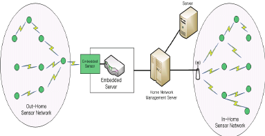
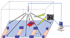
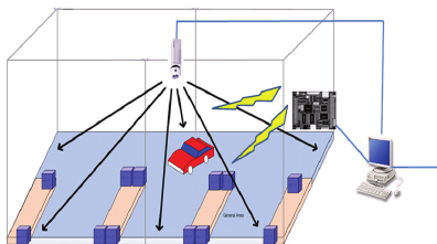
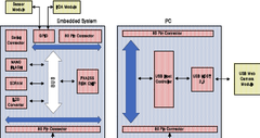
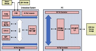
gather and manage home information, but a true home network will be able to gather and manage all environment-related information from both the home and outdoors. Home information generally involves little movement of information and focuses more on data service as compared with outdoor information, which tends to involve more movement of information. Because of this movement and because outdoor information includes a greater range of information types, outdoor information requires a more efficient way to gather data. With this in mind, we designed our network as shown in Fig. 1. In this home network system, both the home network management server and the database management server manage the home and outdoors. For this study, we gave only small consideration to the home communication network; instead we focused on the outdoor communication network for the sensor network. We chose to use a server with a PXA 255 embedded system for the outdoor communication network. This system includes a built-in sensor to gather information from the sensor gathering external environmental information. In order to detect changes in the surrounding environment information, this built-in sensor is attached to the embedded server of the out-home network. A processor for processing the information from the sensor is also attached. The processor is a small device equipped with a wireless transceiver to transfer such information, not as a means of communication but instead with the goal of gathering environment-related information. This is different from existing networks. The wireless sensor network consists of sensor nodes and gateway nodes. The former senses the surrounding environment and then process and transfer data about the events that they sense to sink nodes. The latter, the gateway nodes, gather information from the sensor nodes and transfer it to an external network, such as a TCP/IP network. Information moves both ways through these gateways, so the user can send a query to the sensor field through the sink nodes or receive the gathered data collected in the sensor field. The embedded server, equipped with a built-in sensor, acts as a sensor gateway server. The gateway protocol stack is shown in Fig. 2.[Fig. 1] The ubiquitous home network system model
[Fig. 2] The gateway protocol stack in the embedded server
The embedded server sets and manages the values for the factors governing the network topology of the sensor network, which consists of sensor nodes, sink nodes, and a gateway. The factors governing the network topology include the maximum allowable number of child nodes per sensor node, the RF transmission power of the sensor nodes, the available wireless channels of the sensor nodes, and the wireless bandwidth available for the sensor nodes (e.g. the number of Guaranteed Time Slots of the IEEE 802.15.4 MAC). The sensor network suffers frequent changes in its network topology for a variety of reasons— the battery limitations of the sensor nodes, a disconnected wireless link, the addition of a new sensor node, the movement of sensor nodes, and so on. These changes are monitored in real time and they are displayed in an administrator-friendly graphic form. The sensor network is designed to manage the network topology by independently coping with the network environment with an automatic network restoration function. Either periodically or on an administrator’s command, the sensor nodes transfer to the server the information that is necessary for understanding the network topology. The information, which is assembled into a database, has the following content:
● An H/W-related table is defined to manage H/W information and the state of the sensor nodes in the server. ● Information about sensor network topology is saved and managed in the server. ● The sensor network supporting the mobility of sensor nodes and sink nodes manages the changes in the network topology with movement of the nodes. ● The sensor nodes save information about composition management and, upon request from the server, these nodes deliver this information to the server via the gateway. ● The sensor node and gateway save their IDs. The server synthetically saves and manages the IDs of the sensor nodes and the gateway. These IDs are provided in an administrator-friendly form (alias). For this, the network management system provides a mapping function between an ID and alias.
The server manages the location information of the sensor nodes. Such location information can be entered by the administrator or automatically reported to the server by the location-sensing function. The location information is saved and managed with a connection to the ID of the sensor node of the server. With this method, the embedded server, generally maintained by the home network management server, manages the entire external sensor network. The home network management server operates using the following modules:
3.1 Localization module
sensor nodes associated with a gateway node by means of flooding. ● All the sensor nodes in a cluster broadcast messages to the surrounding nodes by means of flooding. Simultaneously, each of the nodes saves the outgoing node ID/incoming node ID and the received signal strength indicator (RSSI) with the message it received. ● As soon as the flooding is complete, the RSSI values of all of the nodes are saved. The nodes then send the saved RSSI information to the cluster head by means of a response message.
3.2 Time synchronization module
3.3 Network management module
3.4 Fault management module
When a problem arises in the network connection, the
network information is independently initialized and the surrounding network is connected by itself. A forced initialization can be performed with an administrator's command. The administrator may change the duty cycle of sensor nodes as necessary. This duty cycle determines the active state time and sleep state time of the sensor nodes. In the case of applications that periodically gather sensing data, the duty cycle of the sensor nodes is closely related to the sensing data gathering intervals. For a sensor network using the ZigBee protocol, the nodes performing the router function consume more power than the other nodes because of their packet switching function. If such power consumption continues, the nodes performing the router function will run out of battery power faster than the other nodes, reducing the life of the entire sensor network. To avoid this, it is necessary that the remaining battery capacity of a node be sensed. Then if a predefined critical value is reached, the routing function of that node is stopped, and other nodes are directed to take the place of the node with the weak battery. Our system was designed to use sensor nodes more efficiently by gathering large amounts of data by means of image processing, and to collect the surrounding environmental data by means of sensor nodes in order to make up for such a weak point in the sensing network. If the density of sensor nodes is too high—that is, if large numbers of sensor nodes are installed in the same area— this may lead to unnecessary sensing. On the other hand, if sensor nodes are installed accompanied by image sensing, the number of sensor nodes required can be greatly reduced.
4. THE Implementation of the proposed system
4.1 Image Processing
4.2 Image Processing
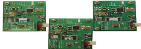
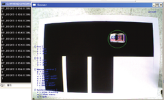
using OpenCV library. - Based on the detected information, the direction that the vehicle is moving is determined and transmitted to the board using socket communication.
4.3 The Vehicle Control
4.4 The Operation of the Implemented System
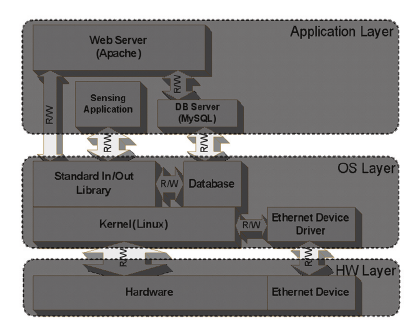
(1) Sensing Application (2) DB Server (3) Web Server
Sensing applications receive data from a sensor gateway connected to the Internet, save the received data from the DB Server to the DB. The DB server stores the sensing information by changing the fixed structure. The web server operates the GUI output of the web type to can recognize easily user as the web browser connect to the server via a web server with receiving the data from the DB server.
Sensor Gateway Sensor Gateway Application R/W R/W R/W R/W Standard Database Modem Voice Files Library In/Out R/W Server Library R/W R/W Device Kernel(Linux) R/W Drivers R/W R/W R/W Hardware (ARM Board) Serial Port LAN R/W R/W Sink Module (Sensor Node) [Fig. 8] The operation of the ubiquitous home network system as implemented
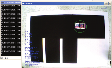
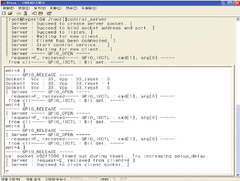
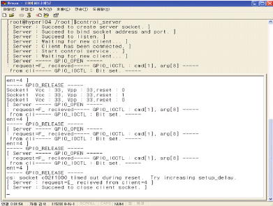
Fig. 9 and Fig. 10 show the operation of the ubiquitous home sensor network as implemented.
[Fig. 9] The operation of the ubiquitous home network system as implemented
[Fig. 10] The operation of the embedded server with the gateway sensor node
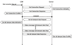
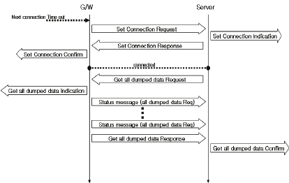
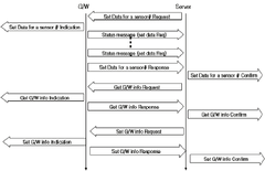
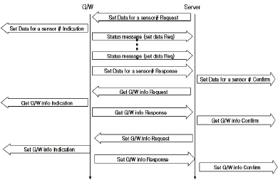
Primitive messages for information exchange between the server and the mobile terminal are defined. Each message is divided into a Get command set that obtains information from the server and a Set command set that sets a certain value in the server. The primitive messages are: Get Sensor Network Lists (Request, Response, Indication, Confirm): Message to get a list of sensor networks accessible from the server Get Node Lists (Request, Response, Indication, Confirm): Message to get a list of the sensor nodes present in a certain sensor network Get Node Info (Request, Response, Indication, Confirm): Message to get information about a certain sensor node Get Node Data (Request, Response, Indication, Confirm): Message to receive data about a certain sensor node Get G/W Info (Request, Response, Indication, Confirm): Message to get information about the sensor gateway that manages a certain sensor network Set Data for a Sensor Node (Request, Response, Indication, Confirm): Message to set and control information about a certain sensor node Set G/W Info (Request, Response, Indication, Confirm): Message to set and control information about a certain sensor gateway Status Message: Message to check the progress of the requested job
(a)
(b)
(c) [Fig. 11] The message flows between the home network management server and the embedded server with the gateway sensor nodel
Communications between a home network management server and an embedded server are carried out with these primitive messages. Each message is properly used according to the job to be performed. The procedure that is followed in performing the job is shown in Figure 11. This is the protocol of the operation of the implemented system. This is the operation to control a car through IrDA in the embedded server with a Web camera. Then, most of the control of the car is exerted through image processing. A very small part, if any, is adjusted via the sensor nodes in the parking lot. For sensor nodes arranged for implementing the system, the entire sensor network is set with the sensor gateway node as the coordinator. Logical 16-bit address information is assigned to each sensor node. Therefore, the action of the embedded system carrying sensor gateway nodes shall be done preferentially. The sensor network topology which was formed automatically could be identified through the LED actuating signal of each arranged sensor node by turning on the power of all the sensor nodes arranged after all ready actions of the sensor gateway are finished. Once the network is formed centered on sensor gateway nodes, the data are transferred to the sensor gateway nodes by turning on the RF mounted on each node every 2 seconds along the route of the network topology, which is essentially in a tree form.
4.5 The simulation of the Implemented System
700 With 1 WEN 600 With 2 WEN With 3 WEN With 4 WEN 500 With 5 WEN With 6 WEN With 7 WEN Times(ms) 400 With With 8 9 WEN WEN 300 With 10 WEN Round 200 100 0 0 20 40 60 80 100 120 The number of sensor nodes [Fig. 12] Round Times vs. the changes of sensor nodes
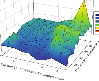
The aim is efficient transmission of all the data to the base station so that the lifetime of the network is maximized in terms of rounds, where a round is defined as the process of gathering all the data from sensor nodes to the base station, regardless of how much time it takes as shown Fig. 12. Fig. 13 shows the hop counts depending on the number of WENs and sensor nodes. As shown in Fig. 13, an increase in the number of WENs reduces the hop counts. Reducing the hop counts leads to a reduction of the remaining energy of the wireless sensor nodes. Therefore, BCDGP is the more efficient energy consumption algorithm.7 62 3 4 5 6 7count 5 Hop 4es3
[Fig. 13] Round Times vs. the changes of sensor nodes in the best case
5. Conclusion
References
- [1] J. Kulik, W. R. Heinzelman, and H. Balakrishnan, “Negotiation-Based Protocols for Disseminating Information in Wireless Sensor Networks,” ACM Wireless Networks, vol. 8, no. 2-3, pp. 169–185, 2002.
- [2] Z. Haas and S. Tabrizi, “On Some Challenges and Design Choices in Ad-Hoc Communications,” in IEEE MILCOM’98, October 1998.
- [3] C. Intanagonwiwat, R. Govindan, and D. Estrin, “Directed Diffusion: A Scalable and Robust Communication Paradigm for Sensor Networks,” in Proceedings of the ACM/IEEE International Conference on Mobile Computing and Networking (MOBICOM), 2000.
- [4] K. Sohrabi, J. Gao, V. Ailawadhi, and G. J. Pottie, “Protocols for Self-Organization of a Wireless Sensor Network,” IEEE Personal Comm. Mag., vol. 7, no. 5, Oct. 2000.
- [5] A. Manjeshwar, D. P. Agrawal, "TEEN: a routing protocols for enhanced efficiency on wireless sensor networks." International Proceedings of 15th Parallel and Distributed Processing Symposium, page 2009-2015, 2001.
- [6]A. Manjeshwar, D. P. Agrawal, "APTEEN: A Protocol for Efficient Routing and Comprehensive Information Retrieval in Wireless Sensor Networks," Proceedings of the 2nd Int. Workshop on Parallel and Distributed Computing Issues in Wireless Networks and Mobile Computing, April 2002.
- [7] S. Lindsey and C. S. Raghavendra, “Pegasis: Power-efficient gathering in sensor information systems,” in IEEE Aerospace Conference, March 2002.
- [8] Huseyin Ozgur Tan, Ibrahim Korpeoglu, “Power Efficient Data Gathering and Aggregation in Wireless Sensor Networks”, ACM SIGMOD Record, Vol. 32, No. 4, Pages 66-71, December, 2003.
- [9] Sung-Hwa Hong, Byounggik Kim, and Doo-Seop Eom, “A Base-station Centric Data Gathering Routing Protocol in Sensor Networks Useful in Home Automation Applications”, IEEE Transaction on Consumer Electronics, Vol. 53, Issue 3, Pages 945-951, August, 2007. Sung-Hwa Hong [Regular member] • Aug. 1996 : Korea Univ., BS • Aug. 2002 : Korea Aerospace Univ., MS • Aug. 2008 : Korea Univ., PhD • Dec. 1997 ∼ May. 2000 : Eastel system LtD., Engineer • March. 2009 ∼ current : Dongyang Technical College., Dept. of Software Eng.,, Lecturer
- <Research Interests> Wireless Network, Ubiquitous, Home Network
- Suk-Yong Jung [Life member] • Feb. 1987 : Seoul National Univ., BS • Aug. 1993 : Kaist, MS • Feb. 2004 : Ajou Univ., PhD • Jan. 1987 ~ Feb. 1996 : LG Information & Telecommunication Ltd., Engineer • Mar. 1996 ~ current : Dongyang Technical College., Dept. of Software Eng., Associate Professor
- <Research Interests> Data Communication, Embedded System, Information Management
