http://dx.doi.org/10.5762/KAIS.2015.16.8.5541 ISSN 1975-4701 / eISSN 2288-4688
Journal of the Korea Academia-Industrial cooperation Society Vol. 16, No. 8 pp. 5541-5549, 2015
Semiconductor wafer exhaust moisture displacement unit
Abstract
This paper introduces a safer and more power efficient heater by using induction heating, to apply to the semiconductor wafer fabrication exhaust gas cleaning system. The exhaust gas cleaning system is currently made with filament heater that generates an endothermic reaction of N2 gas for the removal of moisture. Induction theory, through the bases of theoretical optimization and electronic implementation, is applied in the design of the induction heater specifically for the semiconductor wafer exhaust system. The new induction heating design provides a solution to the issues with the current energy inefficient, unreliable, and unsafe design. A robust and calibrated design of the induction heater is used to optimize the energy consumption. Optimization is based on the calibrated ZVS induction circuit design specified by the resonant frequency of the exhaust pipe. The fail-safe energy limiter embedded in the system uses a voltage regulator through the feedback of the MOSFET control, which allows the system performance to operate within the specification of the N2 Heater unit. A specification and performance comparison from current conventional filament heater is made with the calibrated induction heater design for numerical analysis and the proof of a better design.
Danny Chan 1 , Jonghae Kim 1* 1 Department of Electronic Engineering, Sun Moon University 반도체 웨이퍼 공정 배기가스 수분제어장치 진데니 1 , 김종해 1* 1 선문대학교 전자공학과
요 약 본 논문은 반도체 웨이퍼 공정 배기가스 수분제어장치에 적용하기 위하여 인덕션 히터를 사용해서 안전하고 효율적 인 전력을 사용하는 히터에 대한 설계방법을 제안한다 . 수분을 제거하기 위해서 질소 가스의 흡열 반응을 발생하는 필라멘 트 히터를 이용하여 배기가스 제거 시스템이 만들어진다 . 이론적인 최적화와 전기적인 구현을 통해서 인덕션 이론은 반도 체 웨이퍼 공정 배기가스 시스템을 위한 인덕션 히터 설계과정에 적용되어진다 . 제안한 인덕션 히터 설계는 에너지 측면에 서 비효율적이고 신뢰성이 떨어지며 안전하지 못한 현재의 설계문제에 대한 해결책을 제시한다 인덕션 히터의 강인성과 미세조정 설계기법이 질소 히터의 사양내에서 에너지 소모를 최적화한다 . 최적화는 배기 파이프의 공진주파수에 의해서 특성화된 ZVS(Zero Voltage Switching) 를 기초로 이루어진다 . 시스템에서 끼어진 고장 안전 에너지 리미터는 MOSFET 의 궤환 제어를 통하여 전압 레귤레이터를 사용하고 N2 히터 유닛의 사양이내에서 작동하기 위한 성능을 만족하 도록 한다 . 수치 해석과 설계의 우수성을 위한 기존의 필라멘트 히터와 미세조정한 인덕션 히터 설계의 사양과 성능비교는 제안한 인덕션 히터 설계방법이 우수함을 보여준다 . Keywords : Exhaust Gas, Moisture Displacement Endothermic Reaction, Induction Heating, Hysteresis Effect, Remanence, Coercive Force, Resonant Frequency
1. Introduction
Semiconductor wafer exhaust moisture displacement
unit that processes unwanted by-product gas from the semiconductor wafer fabrication machine. The entire exhaust gas processing system is a cleaning system* Corresponding Author : Jonghae Kim(Sun Moon University) Tel: +82-41-530-2352 email: Received January 30, 2015 Revised (1st May 18, 2015, 2nd July 17, 2015, 3rd July 22, 2015, 4th July 28, 2015 ) Accepted August 6, 2015 Published August 31, 2015
. (fail-safe)
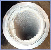
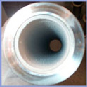
which consists of several units, prior to releasing the gas into the atmosphere. The role of the moisture displacement unit in the cleaning system is to remove moisture within the exhaust gas, which will prevent powders from congesting or clogging the pipes. The current exhaust gas cleaning system uses a device called the N 2 Heater unit to remove moisture. However, the N 2 Heater achieve its goal inefficiently, unreliable and unsafe. Hence, a new design using induction heating improves all aspects of the N 2 Heater’s poor design. Power consumption, unit robustness, and safety are all key improvements with the new design.
2. Preliminary
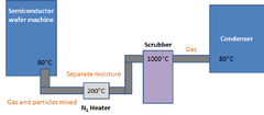
Fig. 1. Semiconductor wafer exhaust gas cleaning system.
The chemicals within the exhaust gas may vary depending on the type of process the semiconductor wafer machine performs. In table 1 below shows the type of process and the different chemicals produced by the wafer machine. Some of these gases listed below are extremely harmful to the environment, and deadly to human. In order to remove or neutralize these harmful gases, various stages are required in the
cleaning process.
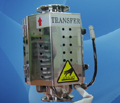
2.1 N 2 Heater
N 2 Heater unit.
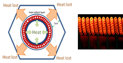
(a) (b)The N 2 Heater removes moisture by injecting N 2 into the pipe and heat the exhaust gas to over 200°C. This allow the moisture to combine with N 2 and form Ammonia (NH 3 ) and oxygen (O 2 ) gas. As shown in Table 1, underlined in bold, NH 3 is a common by-produce for all non-dry processes. The forward reaction of Eq. 1 is an exothermic reaction, where KJ. [11] However, the reverse reaction to Eq.1 is needed for the removal of water vapor. Therefore, an endothermic reaction is inducted by the N 2 Heater unit. The energy required for this endothermic reaction is +1530 KJ, or 425 Wh [6], to remove 6 mol of water. To produce such energy, the N 2 Heater uses a simple heat filament coil heater that wraps around the pipe. N 2 gas is injected from the side of the pipe and then heated to 200°C to create the endothermic reaction of NH 3 .
2.1.1 N 2 Heater inefficiency and safety issue
not dissipated out on external cover.
2.2 Induction Heater objective
3. Methodology
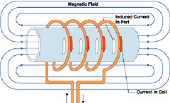
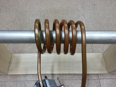
3.1 Induction heating overview
orange, shown on Fig. 5 below.
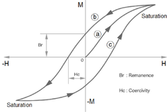
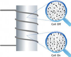
As current passes through the work coil, a magnetic field is created and magnetic hysteresis takes effect [4]. The workpiece is placed within this coil where intense alternating magnetic field passes through it. Heat is generated by hysteresis effect on materials that have significant relative permeability, which are ferromagnetic materials. Iron is most effective material for induction heating. When an external magnetic field is applied to a ferromagnetic material, the atomic dipoles align themselves with it. Even when the field is removed, part of the alignment will be retained: the material has become magnetized. Once magnetized, the magnet will stay magnetized indefinitely. demagnetization requires a magnetic field in the opposite direction. Hence, the high speed flipping in the magnetic field will generate extremely high amount of heat [4].
3.1.1 How hysteresis effect generates heat
3.2 The design
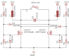
3.2.1 Robust ZVS induction circuitry design
4. Results
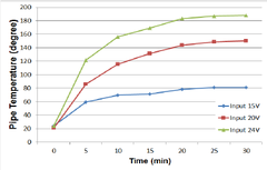
4.1 Temperature results The table 5-7 on the right are the results of different
The table 5-7 on the right are the results of different
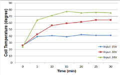
input voltages. Since the temperature is directly controlled by the voltage input, power consumption can be traced and also the rate for which the max temperature is reached. At the resonant frequency of 63kHz, the time for the pipe to heat up to 188°C takes about 30 minutes. Since time is not one of our constraint, by allowing the temperature to charge up can reduce to power consumption. The voltage interval for this test are arbitrary chosen to test the range of the induction heater before maximizing the input voltage and stress out the circuit. Fig. 10 and 11 below illustrates the rising of the temperature in the pipe and the work coil. The input voltage of 24V yields the best temperature output, that is within the specification. In table 7, the pipe highest temperature is recorded to be 75.98°C, any higher input voltage will cause the work coil to be extremely warm and unsafe.
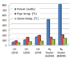
4.2 Power results
4.3 Safety results
5. Conclusion
References
- [1] J. Michael Sherer, Semiconductor Industry: Wafer Fab Exhaust Management, p.13-27, CRC Press, 2010. [DOI]
- [2] Brighter Company. Hot N2 System [Internet]. Brighten.co.kr. c2008. Available From: http://www.brighten.or.kr/gnuboard4/bbs/board.php?bo_ta ble=brighten2_p5. (accessed Nov., 21, 2014) [possible DOI] [alternative DOI]
- [3] Livingston, J. D. "A review of coercivity mechanisms". Journal of Applied Physics, 52 (3): 2541 – 2545, 1981. DOI: http://dx.doi.org/10.1063/1.328996 [DOI]
- [4] Gaunt, P. "Magnetic viscosity and thermal activation energy". Journal of Applied Physics, 59 (12): 4129 – 4132. 1986. DOI: http://dx.doi.org/10.1063/1.336671 [DOI]
- [5] SemiAn Technology. Burn plus wet scrubber for exhaust gas cleaning. [Internet] Crystec.com, Crystec Technology Trading GmbH. c2004. Available From: https://www.crystec.com/ksiburne.htm (accessed Nov., 21, 2014) [possible DOI] [alternative DOI]
- [6] Rajaput, R. K., A Textbook of Electrical Engineering. Introduction to SI Units and Conversion Factors, p.xix-xxi, LAXMI Publications. 2003. [possible DOI] [alternative DOI]
- [7] Jiles, D. C., Atherton, D. L. "Theory of ferromagnetic hysteresis". Journal of Magnetism and Magnetic Materials 61: 48 – 60, 1986. DOI: http://dx.doi.org/10.1016/0304-8853(86)90066-1 [DOI]
- [8] Rudnev, Valery. Handbook of Induction Heating, p.92-93, CRC Press, 2003. [possible DOI] [alternative DOI]
- [9] American Radio Relay League. The ARRL Handbook for Radio Communications 2010. p.5.3-5.9, American Radio Relay League, 2009. [DOI]
- [10] Zhu Zhu Shuangling Technology. IF Inductive Smelting Furnace [Internet]. Zhu Zhou Shuangling Technology Co., LTD. c2002. Available From: http://www.hnsl.net/en/ products_e_show.asp?id=106 (accessed Dec. 4, 2014) [possible DOI] [alternative DOI]
- [11] Haase, R. In Physical Chemistry: An Advanced Treatise, Jost, W., Ed., p 29, Academic: New York, 1971. DOI: http://dx.doi.org/10.1021/j100693a006 Danny Chan [Associate member] •July 2007 : York Univ.(Canada), Earth and Space Science and Engineering, Space Engineering •Sep. 2007 ~ Aug. 2009 : Qauntec Geoscience Inc., Jr. Geophysicist. •Mar. 2013 ~ Present : Sun Moon Univ., Dept. of Electronic Engineering, M. Eng. [possible DOI] [alternative DOI]
- <Research Interests> Control Applications, Geophysics, Space Science [possible DOI]
- Jonghae Kim [Regular member] •Feb. 1995 : Dept. of Electronics, Kyungpook National Univ. (Master’s Degree) •Aug. 1998 : Dept. of Electronics, Kyungpook National Univ. (Ph. D.) •Nov. 1998 ~ Feb. 2002 : Sensor Tech. Research Center (Full-time Researcher) [possible DOI] [alternative DOI]
- •Mar. 2000 ~ Mar. 2001 : Osaka Univ. (Research Fellow) [possible DOI] [alternative DOI]
- •Jan. 2010 ~ Feb. 2011 : Georgia Institute of Tech. (Visiting Research Scholar) [possible DOI] [alternative DOI]
- •Mar. 2002 ~ Current : Dept. of Electronic Eng., Sun Moon Univ. (Professor) [possible DOI] [alternative DOI]
- <Research Interests> Robust Control, Robust Filtering, Signal Processing, Industrial Application Systems [possible DOI] [alternative DOI]